VHDL code for Full Adder With Test bench
VHDL code for Full Adder With Test bench
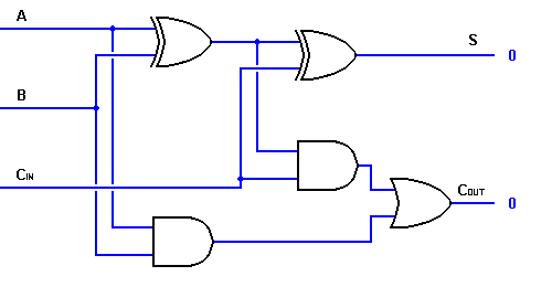
The full-adder circuit adds three one-bit binary numbers (C A B) and outputs two one-bit binary numbers, a sum (S) and a carry (C1). The full-adder is usually a component in a cascade of adders, which add 8, 16, 32, etc. binary numbers.

ENTITY full_adder IS             --- Full Adder
PORT(A,B,Cin: IN BIT ;
  S, Cout : OUT BIT);
END full_adder;
ARCHITECTURE full_adder_beh OF full_adder IS
BEGIN
  PROCESS(A,B,Cin)                -- Sensitive on all the three bits
    VARIABLE temp :BIT;
     BEGIN                       --- DOES the addition in one DELTA time
       temp := A XOR B;
       S <= temp XOR Cin;
       Cout <= (A AND B) OR (temp AND Cin);
     END PROCESS ;
END full_adder_beh;
Test Bench
LIBRARY ieee;
USE ieee.std_logic_1164.ALL;
ENTITY Testbench_full_adder IS
END Testbench_full_adder;

ARCHITECTURE behavior OF Testbench_full_adder IS
 -- Component Declaration for the Unit Under Test (UUT)
 COMPONENT full_adder
 PORT(
 A : IN std_logic;
 B : IN std_logic;
 Cin : IN std_logic;
 S : OUT std_logic;
 Cout : OUT std_logic
 );
 END COMPONENT;
 --Inputs
 signal A : std_logic := '0';
 signal B : std_logic := '0';
 signal Cin : std_logic := '0';
 --Outputs
 signal S : std_logic;
 signal Cout : std_logic;
BEGIN
 -- Instantiate the Unit Under Test (UUT)
 uut: full_adder PORT MAP (
 A => A,
 B => B,
 Cin => Cin,
 S => S,
 Cout => Cout
 );
 -- Stimulus process
 stim_proc: process
 begin
 -- hold reset state for 100 ns.
 wait for 100 ns;
 -- insert stimulus here
 A <= '1';
 B <= '0';
 Cin <= '0';
 wait for 10 ns;
 A <= '0';
 B <= '1';
 Cin <= '0';
 wait for 10 ns;
 A <= '1';
 B <= '1';
 Cin <= '0';
 wait for 10 ns;
 A <= '0';
 B <= '0';
 Cin <= '1';
 wait for 10 ns;
 A <= '1';
 B <= '0';
 Cin <= '1';
 wait for 10 ns;
 A <= '0';
 B <= '1';
 Cin <= '1';
 wait for 10 ns;
 A <= '1';
 B <= '1';
 Cin <= '1';
 wait for 10 ns;
 end process;
END;

Comments
Post a Comment